


SA-1110 Developer’s Manual 79
System Control Module
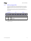
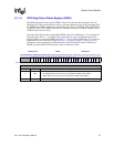
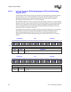
9.1.1.5 GPIO Edge Detect Status Register (GEDR)
The GPIO edge detect status register (GEDR) contains 28 status bits that correspond to the 28
GPIO port pins. When an edge detect occurs on a pin that matches the type of edge programmed in
the GRER and/or GFER registers, the corresponding status bit is set in GEDR. Once a GEDR bit is
set, the CPU must clear it. GEDR status bits are cleared by writing a one to them. Writing a zero to
a GEDR status bit has no effect.
Each edge detect that sets the corresponding GEDR status bit for GPIO pins 0 – 27 can trigger an
interrupt request. Pins 27 – 11 together form a group that can cause one interrupt request to be
triggered when any one of the GEDR status bits 27 – 11 is set. Each of GPIO pins 10 – 0 causes an
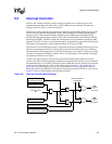
independent first-level interrupt. See the Section 9.2, “Interrupt Controller” on page 9-83 for a
description of the programming of GPIO interrupts. The following table shows a summary of
GEDR; a question mark indicates that the values are unknown at reset.
0h 9004 0018 GEDR Read/Write
31 30 29 28 27 26 25 24 23 22 21 20 19 18 17 16 15 14 13 12 11 10 9 8 7 6 5 4 3 2 1 0
Reserved
ED27
ED26
ED25
ED24
ED23
ED22
ED21
ED20
ED19
ED18
ED17
ED16
ED15
ED14
ED13
ED12
ED11
ED10
ED9
ED8
ED7
ED6
ED5
ED4
ED3
ED2
ED1
ED0
Reset 0 0 0 0 ? ? ? ? ? ? ? ? ? ? ? ? ? ? ? ? ? ? ? ? ? ? ? ? ? ? ? ?
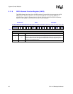
Bits Name Description
nEDn
GPIO edge detect status n (where n = 0 through 27).
0 – No edge detect has occurred on pin as specified in GRER and/or GFER.
1 – Edge detect has occurred on pin as specified in GRER and/or GFER.
31..28 — Reserved