


SA-1110 Developer’s Manual 421
Boundary-Scan Test Interface
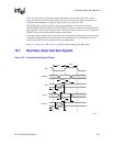
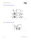
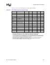
Table 16-1 shows the SA-1110 boundary-scan interface timing guidelines.
Table 16-1. SA-1110 Boundary-Scan Interface Timing
Symbol Parameter Minimum Typical Maximum Units Notes
Tbscl TCK low period 50 ––ns 8
Tbsch TCK high period 50 ––ns 8
Tbsis TDI,TMS setup to TCr 10 ––ns –
Tbsih TDI,TMS hold from TCr 10 ––ns –
Tbsoh TDO hold time 5 ––ns 1
Tbsod TCf to TDO valid ––40 ns 1
Tbsss I/O signal setup to TCr 5 ––ns 4
Tbssh I/O signal hold from TCr 20 ––ns 4
Tbsdh Data output hold time 5 ––ns 5
Tbsdd TCf to data output valid ––40 ns –
Tbsoe TDO enable time 5 ––ns 1,2
Tbsoz TDO disable time ––40 ns 1,3
Tbsde Data output enable time 5 ––ns 5,6
Tbsdz Data output disable time ––40 ns 5,7
Tbsr Reset period 30 ——ns —
Tbsrs TMS setuptoTRr 10 ——ns —
Tbsrh TMS hold from TRr 10 ——ns —
NOTES:
1. Assumes a 25-pF load on TDO. Output timing derates at 0.072 ns/pF of extra load applied.
2. TDO enable time applies when the TAP controller enters the Shift-DR or Shift-IR states.
3. TDO disable time applies when the TAP controller leaves the Shift-DR or Shift-IR states.
4. For correct data latching, the I/O signals (from the core and the pads) must be set up and held with respect
to the rising edge of TCK in the CAPTURE-DR state of the SAMPLE/PRELOAD and EXTEST instructions.
5. Assumes that the data outputs are loaded with the ac test loads.
6. Data output enable time applies when the boundary-scan logic is used to enable the output drivers.
7. Data output disable time applies when the boundary scan is used to disable the output drivers.
8. TCK may be stopped indefinitely in either the low or high phase.