


346 SA-1110 Developer’s Manual
Peripheral Control Module
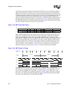
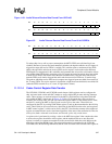
Samples and conversions occur twice in the preceding figure. However, while the counter is decrementing
for the third time, the CPU disables the audio codec by issuing another control register write, represented
by the “Dis” data frame on TXD4. The SFRM pulse following the write causes the disable to take effect,
and the MCP and codec’s audio sample rate counters are stopped and reset to their modulus values.
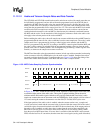
The MCP and the codec’s audio sample rate counters must be enabled coherently so that
synchronization is achieved between the two. This is accomplished by first programming both the
MCP and codec’s sample rate modulus values, then performing a codec control register write to
enable the audio sampling rate counter within the codec. The MCP automatically decodes a write
to the audio codec input and output enable bits, and enables the MCP’s audio sample rate counter at
the same time as the codec’s counter to ensure synchronization.
The UCB1100, UCB1200, and UCB1300 each have an individual data valid bit for audio and
telecom A/D samples. Whenever these bits are set in the data frame returned from the codec to the
MCP, the audio and telecom data is taken from the frame and placed in their respective receive
FIFOs. The UCB1100, UCB1200, and UCB1300 have two different modes of operation to control
the setting of the audio and telecom data valid bits. In the first mode, a data valid bit is set any time
a frame contains “reliable” data (the codec is enabled and at least one A-to-D sample has been
taken). In this mode, once the data valid bit is set, it remains set until the codec A-to-D input is
disabled. In the second mode, the codec only sets the data valid bit corresponding to a new A-to-D
sample. Once the data is transmitted to the MCP within a receive data frame, the data valid bit is
reset to zero for subsequent data frames until a new A-to-D sample is triggered.
11.12.1.3 MCP Transmit and Receive FIFO Operation
The MCP contains four 8-entry x 16-bit FIFOs: one for audio and one for telecom A-to-D samples
received by the MCP, as well as one for audio and one for telecom D-to-A conversions transmitted
to the codec. For the remainder of this description, references made to the audio codec also apply to
the telecom portion of the codec and MCP.
For each incoming data frame, if the audio data valid bit is set, the 16-bit audio A-to-D sample is
extracted and placed in the audio receive FIFO. Note that the MCP also supports a mode in which
the audio data valid bit is ignored after the first conversion has been saved to the FIFO, and the
MCP’s audio sample rate counter is used to signal when a new A-to-D sample has been taken and
is available within the incoming frame. Audio data is transferred from the incoming data frames to
the receive FIFO only if the audio enable bit is set within the MCP’s status register.
The MCP’s audio and telecom sample rate counters are used to trigger when new data is to be
transmitted to the codec. The user should take care in ensuring sample rate counters in the MCP are
synchronized with the respective sample rate counters in the codec as described in preceding sections.
When the audio enable status bit transitions from a 0 to a 1 within the MCP status register, the next
data is taken from the audio transmit FIFO and is placed within the correct field in the MCP’s serial
shifter. This value is then continuously transferred by the MCP in each data frame to the codec. The
codec uses the value only when its audio sample rate counter decrements to zero. After the audio
D-to-A conversion is made, both the codec and the MCP’s audio sample rate counters reload with
their modulus values. This reload triggers the audio transmit FIFO to transfer the next available entry
of data to the MCP’s serial shifter. Again, this value is continuously transmitted to the codec in each
data frame until it is used in the next audio D-to-A conversion.
The width of each entry within the audio and telecom FIFOs is 16 bits. However, for the UCB1100,
UCB1200, and UCB1300, the audio codec’s sample/conversion data size is 12 bits and the telecom
codec’s is 14 bits. Conversions and samples are left justified within the 16-bit audio and telecom
data fields in the MCP frame as well as within the transmit and receive FIFOs.