


SA-1110 Developer’s Manual 419
Boundary-Scan Test Interface
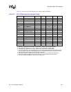
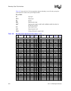
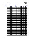
Table 16-2 shows the correspondence between boundary-scan cells and system pins, system
direction controls, and system output enables. The cells are listed in the order in which they are
connected in the boundary-scan register, starting with the cell closest to TDI.
The EXTEST guard values should be clocked into the boundary-scan register (using the
SAMPLE/PRELOAD instruction) before the EXTEST instruction is selected, to ensure that known
data is applied to the core logic during the test. These guard values should also be used when new
EXTEST vectors are clocked into the boundary-scan register.
The values stored in the BS register after power-up are not defined. Similarly, the values previously
clocked into the BS register are not guaranteed to be maintained across a boundary-scan reset
(from forcing nTRST low or entering the Test Logic Reset state).
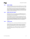
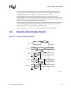
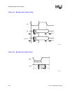
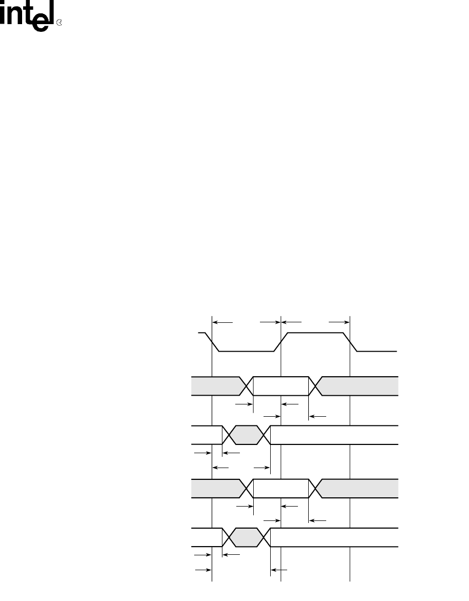
Figure 16-3, Figure 16-4,andFigure 16-5 show the typical timing for the BS register.
16.7 Boundary-Scan Interface Signals
Figure 16-3. Boundary-Scan General Timing
A4772-01
tck
Data In
Data Out
tdo
tms, tdi
Tbscl
Tbsch
Tbsis
Tbsih
Tbsoh
Tbsod
Tbsss
Tbssh
Tbsdh
Tbsdd