


SA-1110 Developer’s Manual 99
System Control Module
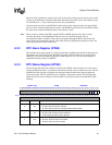
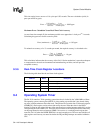
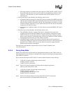
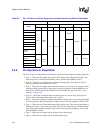
9.4.7 OS Timer Register Locations
Table 9-1 shows the registers associated with the OS timer and the physical addresses used to
access them.
9.5 Power Manager
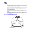
The SA-1110 contains power management logic that controls the transition between three different
modes of operation: run, idle, and sleep. These modes are used to reduce processor power
consumption at times when some functions are not needed, or when the system’s power supply is
low or out of regulation. Each of the respective modes is associated with a reduced level of power
consumption. Idle mode is entered via software. Sleep mode is entered either via software or by
asserting one of two input pins that indicate a power supply fault. Idle mode is exited through an
interrupt. Sleep mode is exited through a preprogrammed wake-up condition. Both modes may be
exited in extreme cases via hardware reset. If none of the power management modes is active and
the SA-1110 is out of reset, then it is said to be in run mode.
9.5.1 Run Mode
Run mode is the normal operating mode of the SA-1110: all power supplies are enabled, all clocks
are running, and every on-chip resource is functional. This is the normal state of operation for the
processor while it is executing code. Under usual conditions, the processor enters run mode after
successful power-up and reset of the part.
9.5.2 Idle Mode
Idle mode allows a software application to stop the CPU when not in use, while continuing to
monitor interrupt service requests both on or off-chip. When an interrupt occurs, the CPU is
reactivated. During idle mode, the SCM, PM, and MPCM are each fully operational.
In idle mode, the CPU clock is stopped. Since the SA-1110 is static, all CPU state information is
saved. This allows the part to be switched back to run mode, starting operation exactly where it left
off. During idle mode, all other on-chip resources are active, including: all system unit modules
(real-time clock, operating system timer, interrupt controller, general-purpose I/O, and power
Table 9-1. OS Timer Register Locations
Address Name Description
0h 9000 0000 OSMR 0 OS timer match registers [3:0]
0h 9000 0004 OSMR 1
0h 9000 0008 OSMR 2
0h 9000 000C OSMR 3
0h 9000 0010 OSCR OS timer counter register
0h 9000 0014 OSSR OS timer status register
0h 9000 0018 OWER OS timer watchdog enable register
0h 9000 001C OIER OS timer interrupt enable register