


SA-1110 Developer’s Manual 91
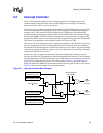
System Control Module
Because of the asynchronous nature of the 1-Hz clock relative to the processor clock, writes to this
counter are controlled by a hardware mechanism that delays the actual write to the counter by up to
one 32-kHz-clock (~ 30 µs) after the processor store is performed.
After the processor writes to the RCNR, all other writes to this register location are ignored until
the new value is actually loaded into the counter. The RCNR may be read at any time. Reads reflect
the value in the counter immediately after it increments or loads.
Note: When a value is written to the RTC registers RTTR or RCNR registers, the value is stored
correctly, but doing a read immediately after the write will read an incorrect value. A
one-instruction delay is needed for the values to propagate through the RTC's logic before the
stored value can be read back correctly. This delay can be accomplished by doing two reads, but
only using the results of the second read.
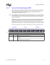
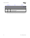
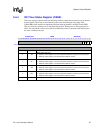
9.3.2 RTC Alarm Register (RTAR)
The real-time clock alarm register is a 32-bit register that is readable and writable by the processor.
Throughout each 1-Hz clock period, RCNR is compared to RTAR. If the two are equal and the
enable bit is set, then the alarm bit in the RTC status register is set. The value in this register is
undefined after the assertion of nRESET.
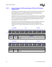
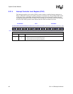
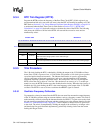
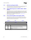
9.3.3 RTC Status Register (RTSR)
The following table shows the location of all bits in the RTSR. All reserved bits are read as zeros
and are unaffected by writes; a question mark indicates that the value is unknown at reset. The AL
and HZ bits in this register are routed to the interrupt controller where they may be enabled to
cause an interrupt. The AL and HZ bits are cleared by writing ones to them. The ALE interrupt
enable bit must be set by software to allow the RTC's assertion of the AL bit and the RTC alarm
interrupt.
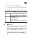
0h 9001 0010 RTSR Read/Write
31 30 29 28 27 26 25 24 23 22 21 20 19 18 17 16 15 14 13 12 11 10 9 8 7 6 5 4 3 2 1 0
Reserved
HZE
ALE
HZ
AL
Reset 0 0 0 0 0 0 0 0 0 0 0 0 0 0 0 0 0 0 0 0 0 0 0 0 0 0 0 0 ? ? ? ?
Bits Name Description
0AL
RTC alarm interrupt detected.
0 – No alarm interrupt has been detected.
1 – An alarm interrupt has been detected (RTNR matched RTAR).
1HZ
1-Hz rising-edge interrupt detected.
0 – No rising-edge interrupt has been detected.
1 – A rising-edge interrupt has been detected.
2ALE
RTC alarm interrupt enable.
0 – The RTC alarm interrupt is not enabled.
1 – The RTC alarm interrupt is enabled.