


SA-1110 Developer’s Manual 415
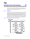
Boundary-Scan Test Interface
16.5.1 EXTEST (00000)
The boundary-scan (BS) register is placed in test mode by the EXTEST instruction. The EXTEST
instruction connects the BS register between TDI and TDO. When the instruction register is loaded
with the EXTEST instruction, all the boundary-scan cells are placed in their test mode of operation.
In the CAPTURE-DR state, inputs from the system pins and outputs from the boundary-scan
output cells to the system pins are captured by the boundary-scan cells. In the SHIFT-DR state, the
previously captured test data is shifted out of the BS register via the TDO pin, while new test data
is shifted in via the TDI pin to the BS register parallel input latch. In the UPDATE-DR state, the
new test data is transferred into the BS register parallel output latch. Note that this data is applied
immediately to the system logic and system pins.
16.5.2 SAMPLE/PRELOAD (00001)
The BS register is placed in normal (system) mode by the SAMPLE/PRELOAD instruction. The
SAMPLE/PRELOAD instruction connects the BS register between TDI and TDO. When the
instruction register is loaded with the SAMPLE/PRELOAD instruction, all the boundary-scan cells
are placed in their normal system mode of operation.
In the CAPTURE-DR state, a snapshot of the signals at the boundary-scan cells is taken on the
rising edge of TCK. Normal system operation is unaffected. In the SHIFT-DR state, the sampled
test data is shifted out of the BS register via the TDO pin, while new data is shifted in via the TDI
pin to preload the BS register parallel input latch. In the UPDATE-DR state, the preloaded data is
transferred into the BS register parallel output latch. Note that this data is not applied to the system
logic or system pins while the SAMPLE/PRELOAD instruction is active. This instruction should
be used to preload the boundary-scan register with known data prior to selecting EXTEST
instructions.
16.5.3 CLAMP (00100)
The CLAMP instruction connects a 1-bit shift register (the BYPASS register) between TDI and TDO.
When the CLAMP instruction is loaded into the instruction register, the state of all output signals is
defined by the values previously loaded into the boundary-scan register. A guarding pattern
(specified for this device at the end of this section) should be preloaded into the boundary-scan
register using the SAMPLE/PRELOAD instruction prior to selecting the CLAMP instruction.
In the CAPTURE-DR state, a logic 0 is captured by the bypass register. In the SHIFT-DR state, test
data is shifted into the bypass register via TDI and out via TDO after a delay of one TCK cycle.
Note that the first bit shifted out will be a zero. The bypass register is not affected in the
UPDATE-DR state.