


SA-1110 Developer’s Manual 331
Peripheral Control Module
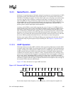
receiver each time the start bit is detected on the receive pin and each bit of the receive data stream
is sampled on the eighth clock of the divide by 16 counter (halfway through the bit period). The
resultant baud rate, given a specific BRD value or required BRD value and given a desired baud
rate, can be calculated using the following two respective equations, where BRD is the decimal
equivalent of the binary value programmed within the bit field:
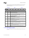
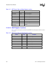
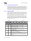
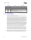
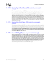
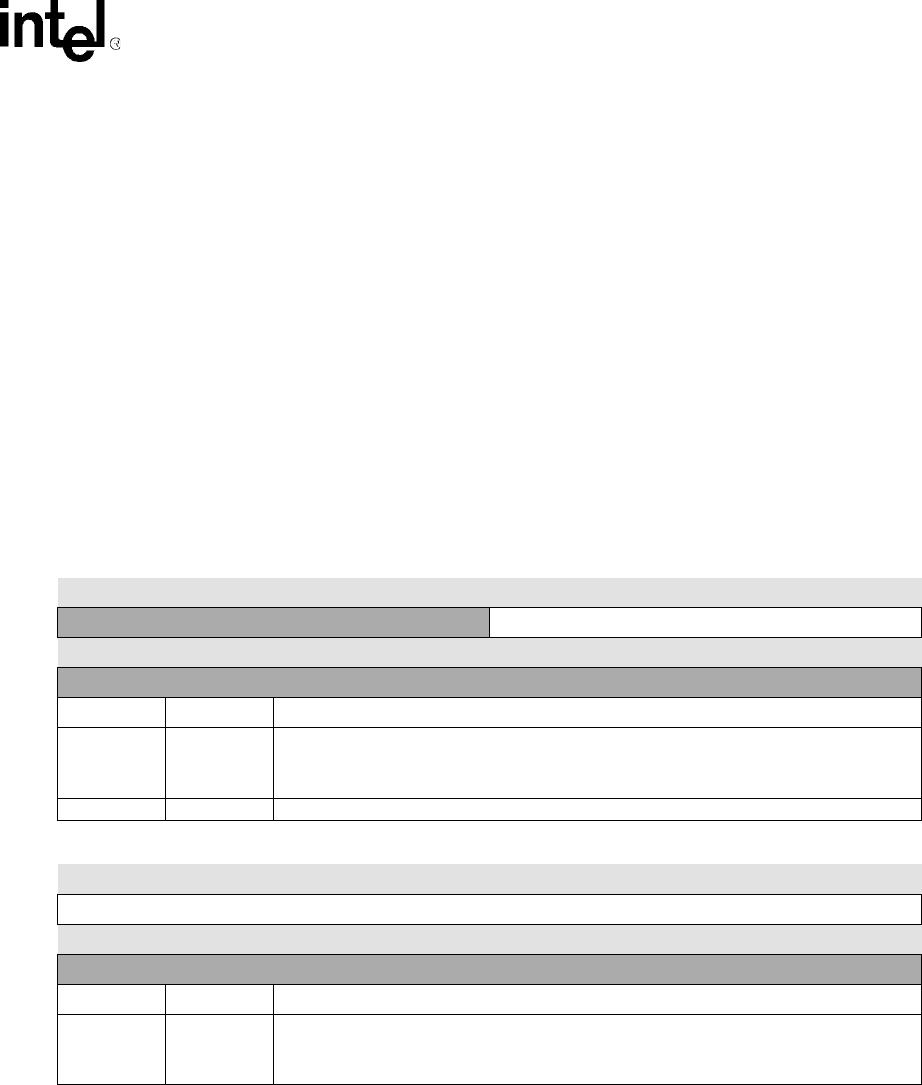
The following tables show the bit locations corresponding to the baud rate divisor field that is split
between two 8-bit registers. The upper four bits of BRD reside within UTCR1 and the lower eight
bits reside within UTCR2. The UART must be disabled (RXE=TXE=0) whenever these registers
are written. The reset state of the BRD field is unknown (indicated by question marks) and must be
initialized before enabling the UART. Note that writes to reserved bits are ignored and reads return
zeros.
11.11.5 UART Control Register 3
UART control register 3 (UTCR3) contains six different bit fields that control various functions
within the UART.
BaudRate
3.6864
6
×10
16
x BRD 1+()
---------------------------------------=
BRD
3.6864
6
×10
16
xBaudRate
----------------------------------------1–=
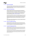
0h 8005 0004 UTCR1 Read/Write
7 6 5 4 3 2 1 0
Reserved BRD 11..8
Reset
0 0 0 0 ? ? ? ?
Bits Name Description
3..0 BRD 11..8
Baud rate divisor.
Encoded value (from 0 to 4095) used to generate the baud rate of the UART.
Baud Rate = 3.6864x10
6
/(16x(BRD+1)), where BRD is a decimal value.
7..4 — Reserved.
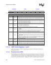
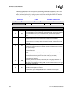
0h 8005 0008 UTCR2 Read/Write
7 6 5 4 3 2 1 0
BRD 7..0
Reset
? ? ? ? ? ? ? ?
Bits Name Description
7..0 BRD 7..0
Baud rate divisor.
Encoded value (from 0 to 4095) used to generate the baud rate of the UART.
Baud Rate = 3.6864x10
6
/(16x(BRD+1)), where BRD is a decimal value.