DES-7200 Configuration Guide Chapter 2 Configuring BGP IP VPN
2-57
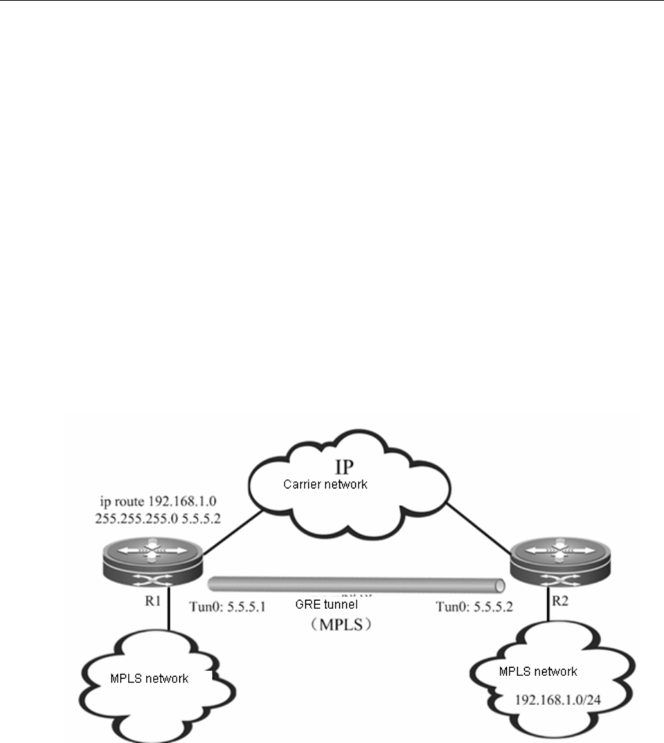
As shown in Fig 18, R1 and R2 are connected to a MPLS network respectively, while both
routers are interconnected via a carrier network (IP). The GRE tunnel allows both endpoints (R1
and R2) to use the carrier network (IP) to transmit MPLS packets, so that two separated MPLS
networks can be connected. GRE tunnel is the point-to-point logical link between R1 and R2. It
bypasses the carrier network (IP) and becomes one part of the MPLS network, so that the MPLS
networks at both ends of the tunnel can maintain continuity. Considering GRE tunnel as a
point-to-point link, IGP protocol can run on the link, while LDP can also distribute labels between
R1 and R2.
Introduction of tunnel traffic
In either carrier network (IP) or MPLS network, the traffic forwarding is driven by router.
Therefore, dynamic routing protocol needs to be run in the carrier network (IP) and MPLS
network. There are two possible scenarios: single routing instance and dual routing instances.
Single routing instance
Fig 19 Single routing instance
In this scenario, MPLS network and carrier network (IP) are in the same routing instance, and the
entire network is of plane form, as shown in Fig 19. By default, since the Metric value of GRE
tunnel is far greater than the ordinary link, no traffic will be introduced into the GRE tunnel (which
means GRE tunnel is not the next-hop interface of any route). Therefore, we must configure
static routes in order to introduce MPLS traffic into the GRE tunnel. The static routes must be


