DES-7200 Configuration Guide Chapter 5 DHCP Relay Configuration
5-12
5.5 Typical DHCP Relay
Configuration Example
5.5.1 Topological Diagram
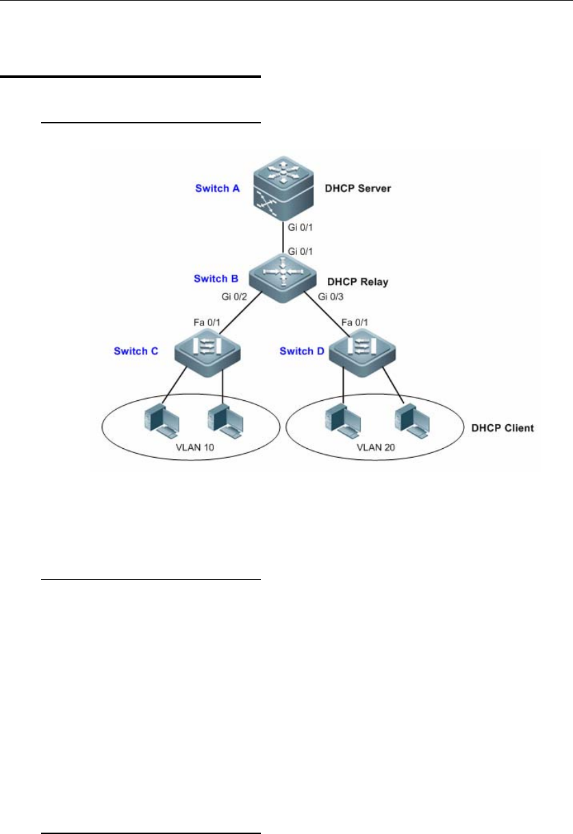
Diagram for DHCP Relay configuration
5.5.2 Application
Requirements
As shown above, Switch C and Switch D are access devices connecting with
PC users belonging to VLAN 10 and VLAN 20. Switch B is the gateway device,
while Switch A is the core routing device. The following requirements must be
met:
z Switch A can serve as DHCP Server allocating dynamic IP addresses to
VLAN users.
z The users connecting to Switch C and Switch D can acquire dynamic IP
addresses across the network segment.
5.5.3 Configuration Tips
1. Configuring DHCP Server: On Switch A, create DHCP address pools for
users from VLAN 10 and VLAN 20 respectively, and enable DHCP Server
(relevant configurations of DHCP Server can be found in "DHCP
Configuration").


