


DES-7200 Configuration Guide Chapter 8 TPP Configuration
8-6
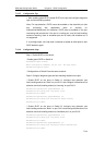
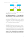
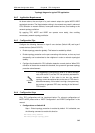
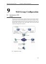
Topologyl diagram for typical TPP application
8.6.2 Application Requirements
As shown above, the core layer of a park network adopts the typical MSTP+VRPP
topological structure. The illegal attacks existing in the network may result in abnormal
CPU utilization on network devices, frame path blocked and etc, thus leading to the
network topology oscillation.
By applying TPP, MSTP and VRRP can operate more stably, thus avoiding
unnecessary network topology oscillation.
8.6.3 Configuration Tips
Configure the following features on layer-3 core devices (Switch A/B) and layer-2
access devices (Switch C/D/E/F):
¾ Enable topology protection globally. This feature is enabled by default.
¾ Enable topology protection on the port connecting with devices, so that any local
abnormality can be advertised to the neighbors in order to maintain topological
stability.
¾ Configure the threshold for CPU utilization detection on each device. When CPU
utilization of the device exceeds this threshold, the system will generate topology
protection advertisement.
Note
It is suggested to configure this value to an above-average
ratio, such as 50-70, so that TPP can precisely estimate the
network situation. If this value is too low, the network
topology cannot be switched due to the alert of TPP when it
becomes necessary; if this value is too high, the system may
be too busy to generate TPP alert, resulting in the failure of
TPP function.
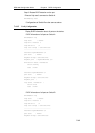
8.6.4 Configuration Steps
Only TPP configurations will be introduced below. For relevant configurations of
MSTP+VRPP, please refer to "MSTP Configuration" and "VRRP Configuration" in the
manual.
¾ Configurations on Switch A/B
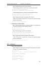
Step 1: Global topology protection is enabled by default. If it is disabled, use
the following command to enable this function.
DES-7200# config terminal
DES-7200(config)# topology guard