DES-7200 Configuration Guide Chapter 8 VRF
Configuration
8-7
8.6 Typical MCE Configuration Example
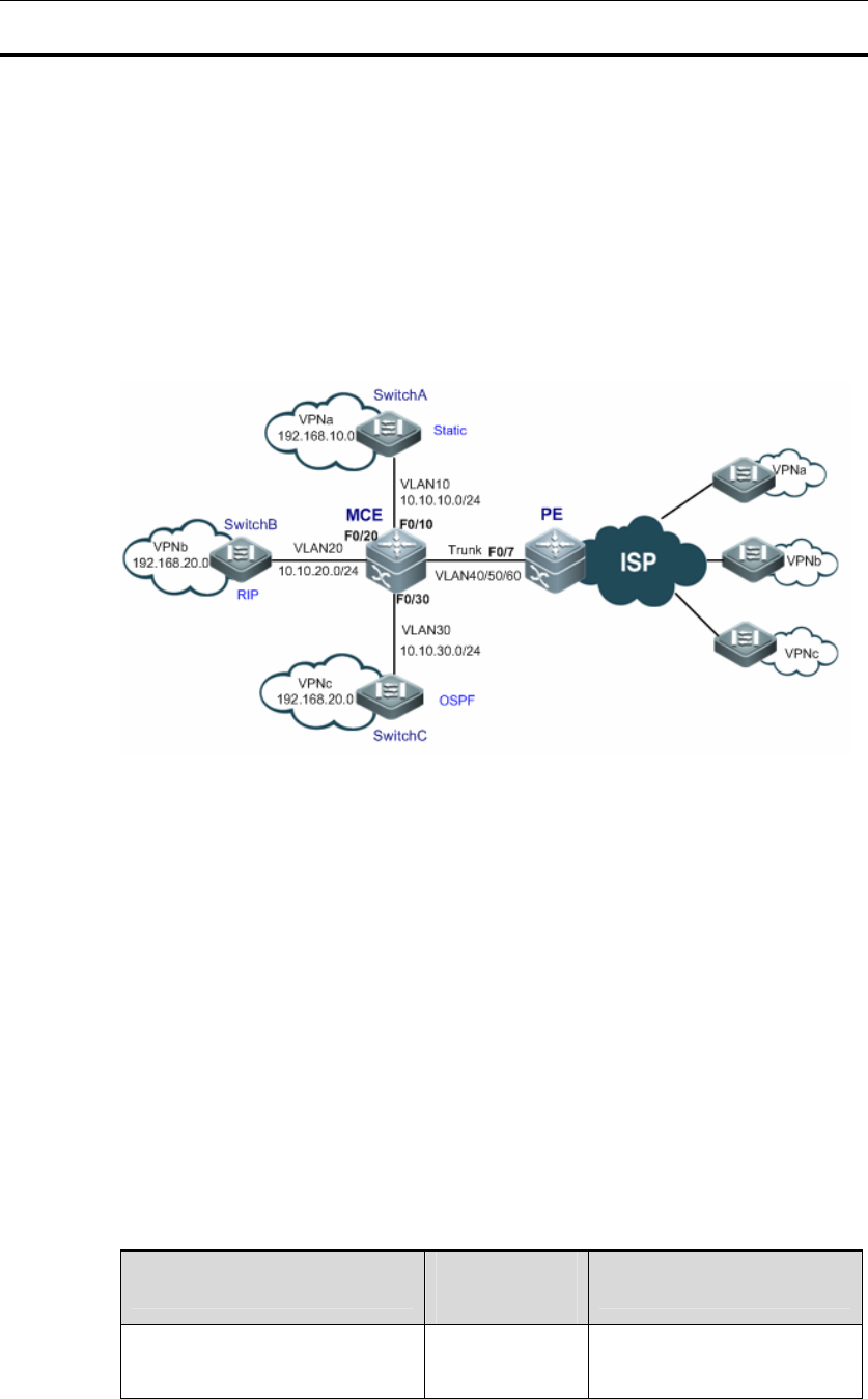
Topological Diagram
As shown below, different sites of VPNa, VPNb and VPNc need to exchange
information across the backbone network.
Each VPN site accesses PE through MCE device.
Configure a static route between MCE device and VPNa; configure RIP
protocol between MCE and VPNb to exchange routes; configure OSPF
protocol between MCE and VPNc to exchange routes.
Topological diagram for typical MCE application
Application Requirements
It is required that MCE device shall be able to isolate the routes of respective
VPNs, and advertise the routes of respective VPNs to PE device by
configuring static routing, RIP routing protocol and OSPF routing protocol.
Overlapped IP addresses are allowed in different VPNs.
Configuration Tips
Configuring multiple VRF instances on MCE and PE device, so that the routes of
different VPNs can be isolated from each other. Configurations include the
following two steps:
Configure VRF instances and associate with the corresponding interfaces
Interface
Associated
VRF
IP address of interface
VPNa-connecting interface of
MCE device (SVI 10)
VPNa 10.10.10.3


