DES-7200 Configuration Guide Chapter 8 IGMP Snooping
Configuration
8-34
------------------ --------------------- ---------
FastEthernet 0/3 1 4294967294
FastEthernet 0/4 0 100
Step 5: Send IP multcast traffic with group address being 224.2.2.2 through the
Source, and reqeust multicast traffic on port Fa 0/2 of Switch B. Display the group
members of Switch A and CDA table of Switch B.
! Switch A
SwitchA#show ip igmp groups
IGMP Connected Group Membership
Group Address Interface Uptime Expires Last Reporter
224.2.2.2 VLAN 1 00:00:51 00:03:55 0.0.0.0
! Switch B
SwitchB#show ip igmp snooping gda-table
Multicast Switching Cache Table
D: DYNAMIC
S: STATIC
M: MROUTE
(*,224.1.1.1, 1):
VLAN(1) 2 OPORTS:
FastEthernet 0/1(M)
FastEthernet 0/2(S)
(*,224.2.2.2, 1):
VLAN(1) 2 OPORTS:
FastEthernet 0/1(M)
FastEthernet 0/2(D)
8.4.2 Example of IVGL-SVGL mode Configuration
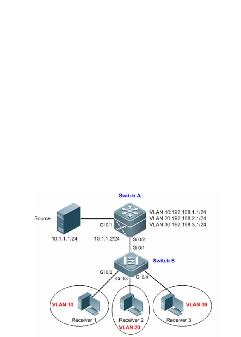
Topological Diagram
Figure5 Diagram for IVGL mode
Application Requirements
As shown above, Switch A is a multicast routing device directly connected with a
multicast source, and Switch B is a layer-2 access device connected with multiple
multicast receivers which belong to different VLANs. The primary requirements
are shown below:


