


DES-7200 Configuration Guide Chapter 5 RERP Configuration
5-13
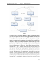
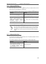
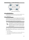
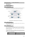
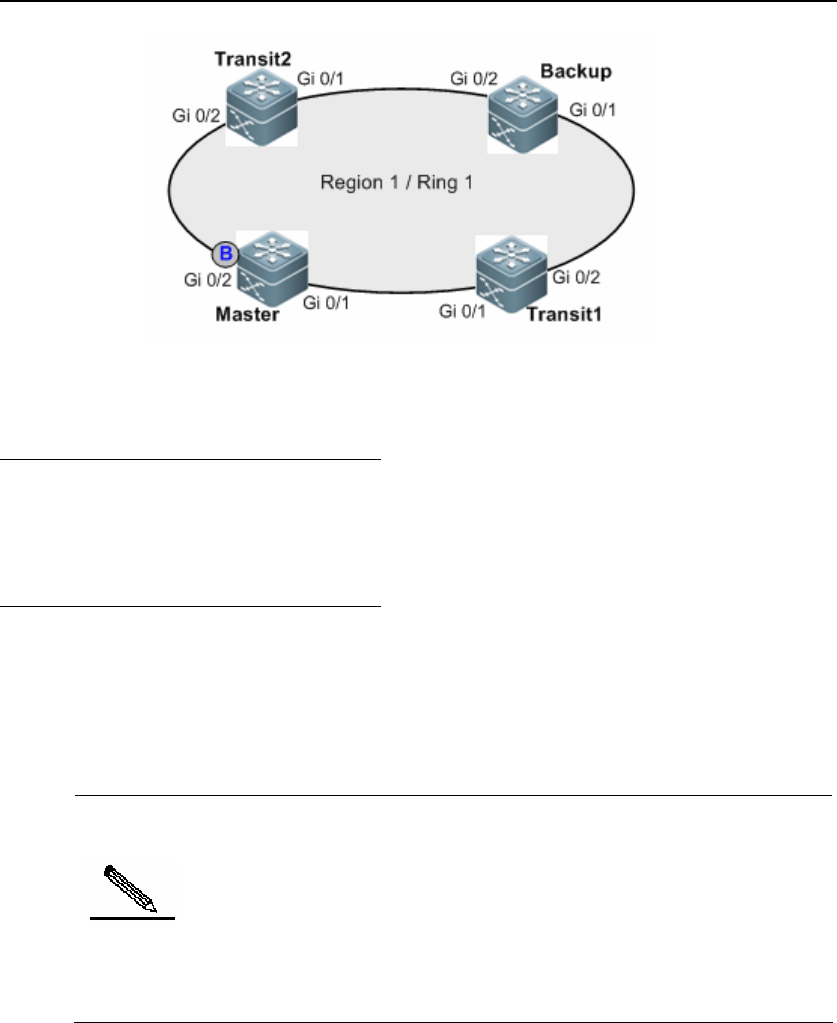
Topological diagram for RERP single ring
5.4.1.2 Application Requirements
It is required that this core network shall be able to implement rapid switchover upon
link failure and avoid the failure of entire ring caused by single point failure.
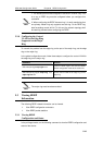
5.4.1.3 Configuration Tips
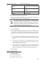
Four core devices use RERP ring to realize ring protection of the sci-tech core network
and rapid switchover in case of any link failure. The RERP ports (G0/1 and G0/2) of all
nodes on the ring belong to the same control VLAN (VLAN 4000). G0/1 is configured
as the primary port, while G0/2 is configured as the secondary port. The timer uses the
default value. Roles of respective devices on the ring are shown above.
Note
On the RERP ring, the interface joining RERP ring must be a Trunk
port, and its Native Vlan must be configured to the control VLAN of
corresponding ring. In this example, all interfaces (G0/1 and G0/2)
joining the RERP ring have been configured as Trunk ports, the Native
VLAN has been configured to control VLAN (VLAN 4000). For detailed
configurations, please refer to the section of "Interface Configuration"
as shown in this manual.
Before configuring RERP, we must identify the roles of respective devices on RERP
single ring, and then implement RERP configuration on respective devices according
to the following steps:
1. Define the RERP domain.
2. Define the RERP ring and configure the role of this device on RERP ring, the
control VLAN to which it belongs and the primary and secondary ports.
3. Enable the RERP.