DES-7200 Configuration Guide Chapter 10 MSTP Configuration
10-11
Since traditional spanning tree protocols are not related to a VLAN, the
following problems may occur in a specific network topology.
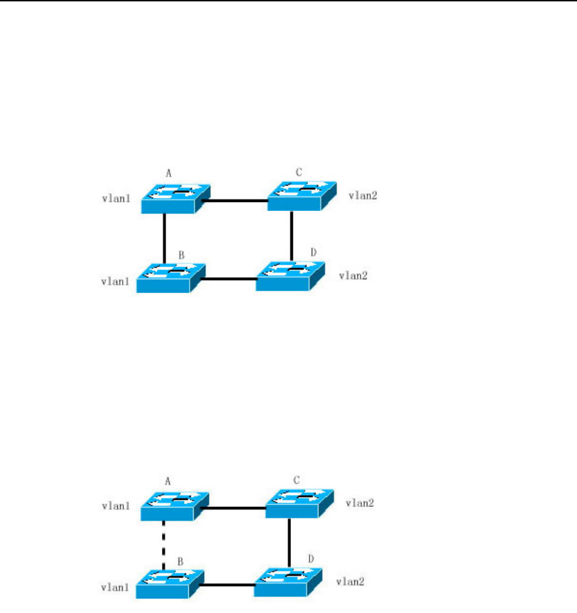
As shown in Figure 14, Switches A and B are located in Vlan1, and switches C
and D in Vlan2. They form a loop.
Figure-14
If the cost of the path from Switch A through Switch C, Switch D to Switch B is
smaller than that of the direct path from Switch A to Switch B, the latter path will
be torn down, as shown in Figure 15. Packets in Vlan1 can not be forwarded
because Switches C and D do not contain Vlan1. In this way, Vlan1 of Switch A
cannot communicate with Vlan1 of Switch B.
Figure-15
The MSTP protocol is developed to address this problem. It partitions one or
more vlans of the switch into an instance, so the switches with the same
instance configuration form a region (MST region) to run a separated spanning
tree (this internal spanning-tree is referred to as the IST). The MST region is
equivalent to a large device, which executes the spanning tree algorithm with
other MST regions to obtain a whole spanning tree, referred to as the common
spanning tree (CST).
With this algorithm, the above mentioned network can form the topology shown
in Figure 16. Switches A and B are within the MSTP region 1 without a loop, so
no path is discarded. This is also the case in the MSTP region 2. Region 1 and
region 2 serve as two large devices respectively. There is a loop between them,
so one path is discarded according to related configuration.
