DES-7200 Configuration Guide Chapter 4 OSPF
Configuration
4-36
4.4 OSPF Configuration Examples
4.4.1 Multi-area OSPF Configuration Example
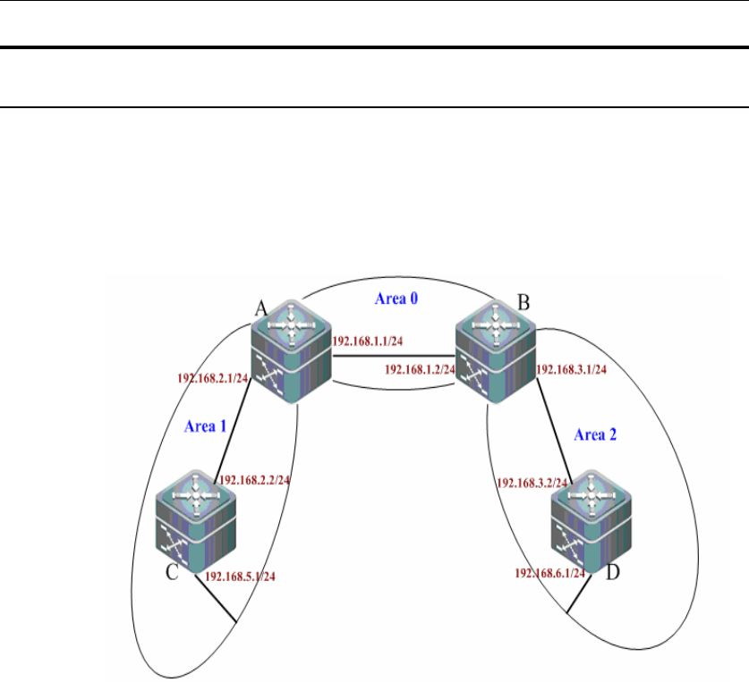
Topological diagram
The following figure shows the networking diagram for OSPF autonomous system.
The entire autonomous system is divided into three areas: area 0, area 1 and
area 2. OSPF protocol is running on respective devices.
z Networking diagram for multi-area OSPF configuration
Application needs
Configure Switch C and Switch B as area border routers (ABR) and Switch C and
Switch D as intra-AS devices. Through OSPF basic configurations, every switch
can successfully learn the routes to all network segments.
Configuration tips
Configure the IP address of respective interfaces
Enable routing (disabled by default)
Create OSPF routing process
Specify the IP address range associated with this routing process and the
OPPF area to which these IP addresses belong.
Configuration Steps
¾ Configure A
Step 1: Configure IP address of the interface


