


DES-7200 Configuration Guide Chapter 4 OSPF
Configuration
4-58
Step 4: Display OSPF routing information on devices in other areas. Key point:
whether there is any AS external route imported by NSSA area.
SwitchA#show ip route ospf
O E2 172.10.10.0/24 [110/20] via 192.168.1.2, 02:08:08, GigabitEthernet 0/1
O E2 191.10.10.0/24 [110/20] via 192.168.2.2, 03:18:35, GigabitEthernet 0/2
O IA 192.168.3.0/24 [110/2] via 192.168.1.2, 5d,17:59:01, GigabitEthernet 0/1
O 192.168.5.0/24 [110/2] via 192.168.2.2, 03:31:25, GigabitEthernet 0/2
O IA 192.168.6.0/24 [110/3] via 192.168.1.2, 02:08:09, GigabitEthernet 0/1
From the above information, we can see that an AS external route imported by
NSSA area is contained in the routing table of Switch A.
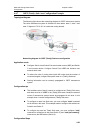
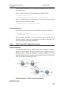
4.4.9 OSPF Inter-area Route Summarization Configuration Example
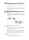
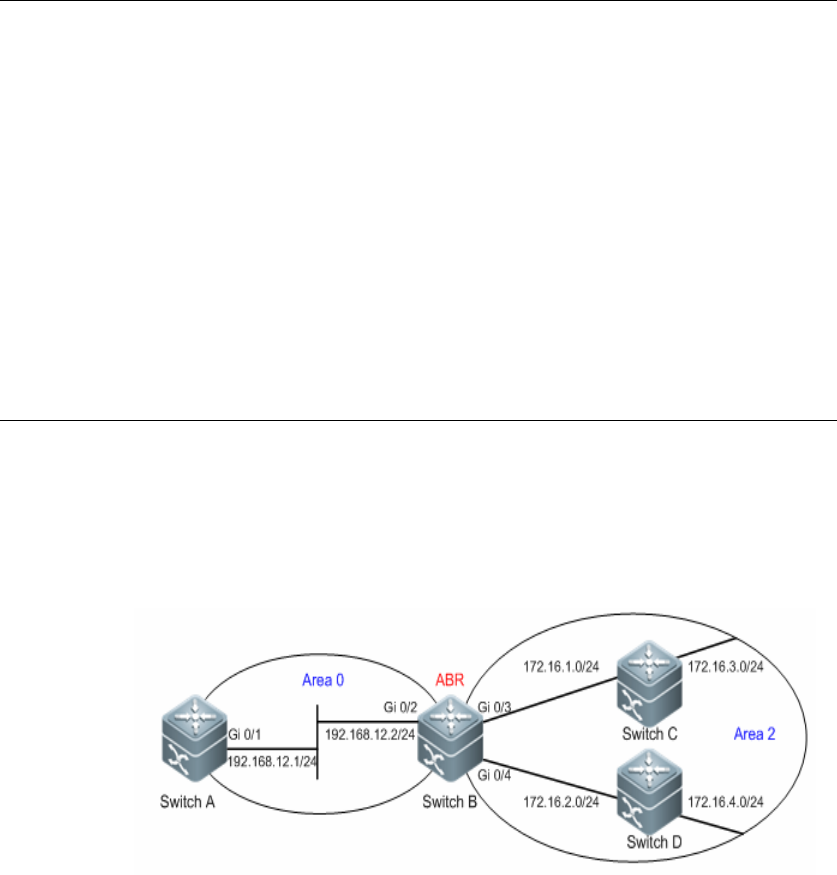
Topological diagram
The following figure shows the topological diagram for OSPF autonomous system,
in which segment 192.168.12.0/24 belongs to Area 0 and segments
172.16.1.0/24, 172.16.2.0/24, 172.16.3.0/24 and 172.16.4.0/24 belong to Area 2.
OSPF inter-area route summarization configuration example
Application needs
To reduce the size of routing table, configure Switch B so that it will only advertise
the summary route of four network segments (172.16.1.0/24, 172.16.2.0/24,
172.16.3.0/24 and 172.16.4.0/24) instead of advertising the routes of these four
segments.
Configuration tips
1. Since segments 172.16.1.0/24, 172.16.2.0/24, 172.16.3.0/24 and
172.16.4.0/24 are consecutive address ranges, we can configure route
summarization on the area border device (Switch B) to alleviate route
computation. The command for configuring OSPF inter-area route summarization
is "area range".