


DES-7200 Configuration Guide Chapter 4 OSPF
Configuration
4-52
4.4.7 OSPF (Totally) Stub Area Configuration Example
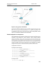
Topological diagram
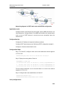
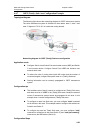
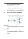
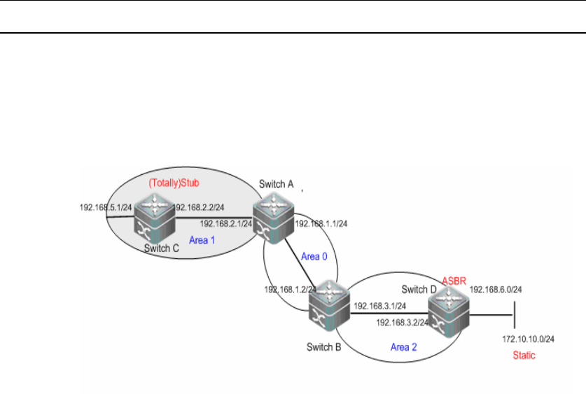
The following figure shows the networking diagram for OSPF autonomous system.
The entire autonomous system is divided into three areas: area 0, area 1 and
area 2. Segment 172.10.10.0 is outside the routing domain.
Networking diagram for OSPF (Totally) Stub area configuration
Application needs
Configure Switch A and Switch B as area border routers (ABR) and Switch
C as intra-area device. Configure Switch D as ASBR and introduce one
external static route.
To reduce the size of routing table inside AS border and the number of
routes exchanged, configure the specific area to a (Totally) Stub area.
Routing information can be correctly propagated in OSPF autonomous
system.
Configuration tips
The backbone area (Area 0) cannot be configured as (Totally) Stub area,
and there must be no ASBR in the (Totally) Stub area, namely the external
routes of autonomous system cannot be propagated in this area. In this
example, Area 1 can be configured as a (Totally) Stub area.
To configure an area into Stub area, you must configure "stub" command
on all devices in this area. This example needs to configure this attribute on
Switch A and Switch C.
To configure an area into Totally Stub area, you must configure "stub"
command on all devices in this area (Switch C) and "stub [no-summary]"
command on the ABR device (Switch A).
Configuration Steps