DES-7200 Configuration Guide Chapter 10 MSTP Configuration
10-14
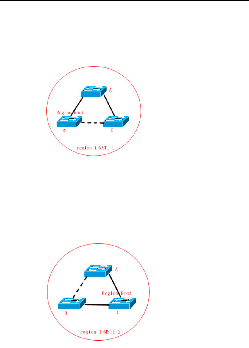
discarded according to other parameters. Hence, for the VLAN group of
instance 1, only the path from switch A to switch B and switch A to switch C are
available, which break the loop of the VLAN group.
Figure-18
As shown in Figure 19, switch B with the highest priority is selected as the
region root in the MSTI 2 (instance 2). Then, the path between switch B and
switch C is discarded according to other parameters. Hence, for the VLAN
group of instance 2, only the path from switch A to switch B and switch B to
switch C are available, which break the loop of the VLAN group.
Figure-19
It should note that the MSTP protocol is not concerned on which VLAN a port
belongs to, so users should configure corresponding path costs and priorities
for ports according to actual VLAN configuration to prevent the MSTP protocol
from breaking the loop unnecessarily.


