DES-7200 Configuration Guide Chapter 12 QinQ Configuration
12-36
12.4 Typical BPDU Tunnel
configuration example
12.4.1 Topological diagram
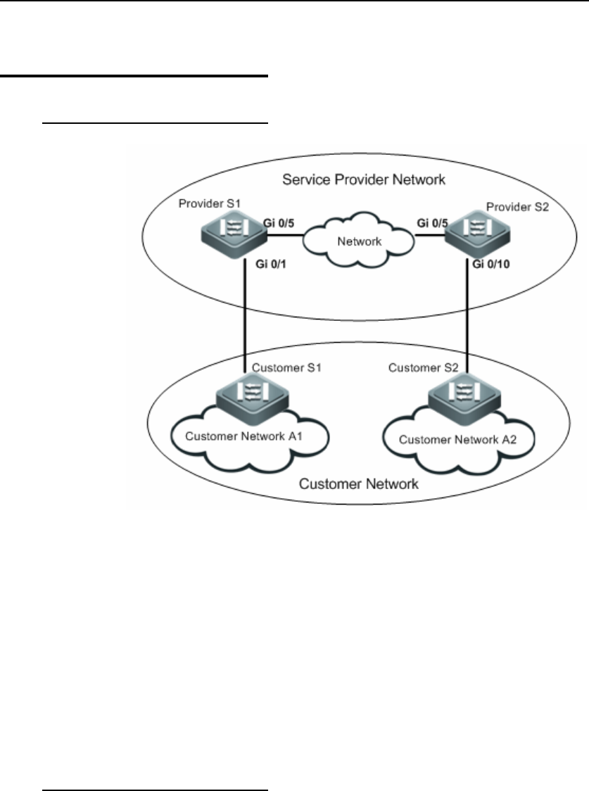
Figure 11 Topological diagram for BPDU Tunnel application
As shown above, the upper part is the provider network, and the lower part is
the user network. The provider network includes edge devices of Provider S1
and Provider S2. Customer Network A1 and Customer Network A2 are two sites
of the same user at different geographical locations. Customer S1 and
Customer S2 are the access devices connecting user network with provider
network, and access the provider network through Provider S1 and Provider S2
respectively.
12.4.2 Application
requirements
1. Packets from user network are transmitted over provider network in
VLAN200.
2. Customer Network A1 and Customer Network A2 at different geographical
locations can participate in unified spanning tree calculation across the provider
network without affecting the provider network.


