


DES-7200 Configuration Guide Chapter 10 MSTP Configuration
10-13
The MSTP BPDU carries above information. If a device has received the same
MST configuration information of the BPDU as that of itself, it considers that the
device connecting to this port belong to the same MST region as itself.
You are recommended to configure the instance-vlan table while the STP
protocol is disable, and then enable the MSTP protocol to ensure the stability
and convergence of the network topology.
10.1.2.2 Spanning Tree within a MSTP
region (IST)
After MSTP regions are partitioned, a root bridge is elected for every instance
within a region and the port role is determined for every port on a switch. A port
is forwarded or discarded within an instance depneds on its role.
In this way, the IST (Internal Spanning Tree) is formed by exchanging the MSTP
BPDU message, and various instances have their own spanning trees (MSTI).
The spanning tree corresponding to the instance 0 is referred to as the CIST
(Common Instance Spanning Tree) in conjunection with CST. That is to say,
each instance provides each VLAN group with a single network topology
without loop.
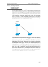
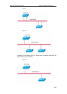
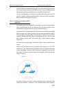
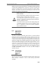
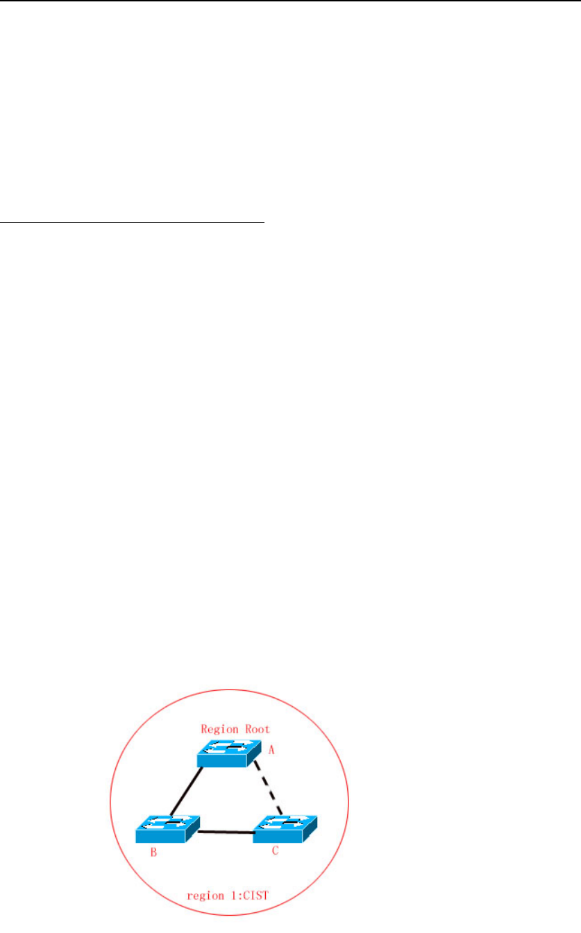
As shown in the following figure, Switches A, B and C form a loop within the
region 1.
Switch A with the highest priority is selected as the region root in the CIST
(instance 0). Then, the path between Switches A and C is discarded according
to other parameters. Hence, for the VLAN group of instance 0, only the path
from switch A to B and switch B to switch C are available, which break the loop
of the VLAN group.
Figure-17
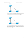
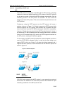
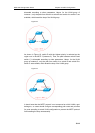
As shown in Figure 18, switch C with the highest priority is selected as the
region root in the MSTI 1 (instance 1). Then, the path between switch A and B is