DES-7200 Configuration Guide Chapter 9 Share VLAN Configuration
9-5
(belonging to VLAN 10), making sure the network resources won't be wasted
(namely users in VLAN 3 cannot receive the reply packets sent by video
server).
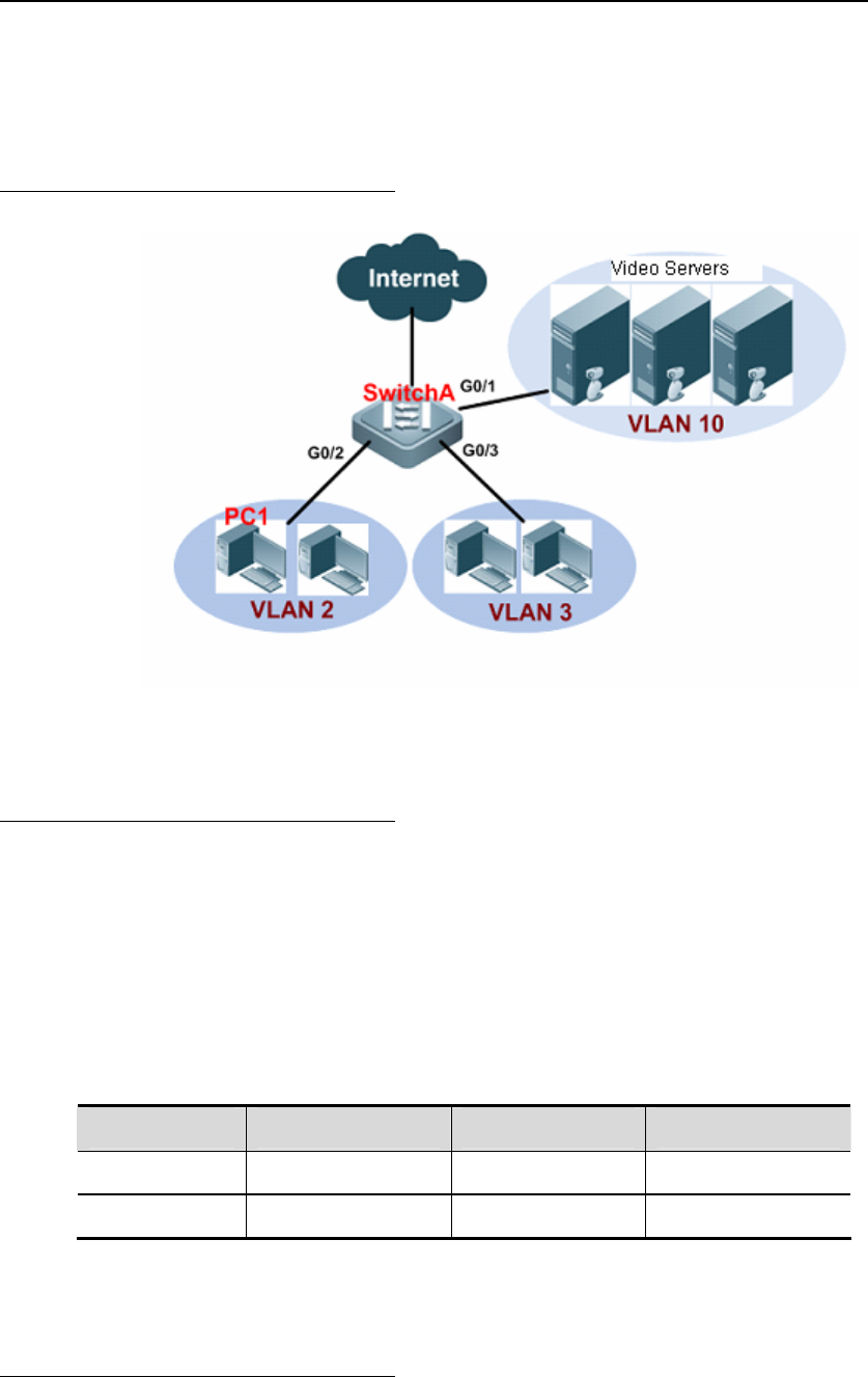
9.5.1.2 Network Topology
SHARE VLAN video-on-demand application
9.5.1.3 Configuration Tips
To meet the needs, we must configure VLAN 10 as a SHARE VLAN on
SwitchA.
After PC1 has requested the video program, the video server will reply to the
request. When packets reach SwitchA, the switch will insert VLAN 10 Tag
according to the PVID value.
On SwitchA, configure VLAN10 as the SHARE VLAN; the addresses learned by
the switch will be:
Vlan MAC Address Type Interface
2 PC1-MAC DYNAMIC G0/2
10 PC1-MAC DYNAMIC G0/2
Packets will be directly sent to PC1 through G0/2, and other users won't be able
to receive these reply packets.
9.5.1.4 Configuration Steps
1. On SwitchA, configure G0/2 as a hybrid port (default VLAN is 2, and the
allowed UNTAG VLANs include VLAN 2 and VLAN 10); configure G0/3 as a


