


DES-7200 Configuration Guide Chapter 10 MSTP Configuration
10-15
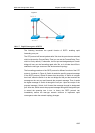
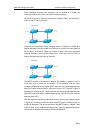
10.1.2.3 Spanning Tree between MSTP
regions (CST)
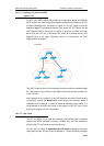
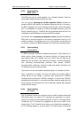
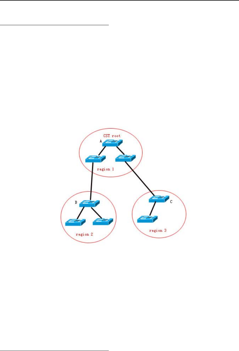
For CST, each MSTP region is equivalent to a large-sized device, and different
MSTP regions also form a large-sized network topology tree, referred to as CST
(common spanning tree). As shown in Figure 20, for CST, switch A with the
smallest bridge ID is selected as the root of the entire CST (CST Root) and the
CIST Regional Root in this region. In Region 2, since the root path cost from
switch B to the CST root is the lowest one, switch B is selected as the CIST
Regional Root in this region. Similarly, switch C is selected as the CIST
Regional Root in Region 3.
Figure-20
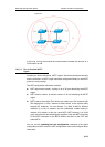
The CIST Regional Root is not necessarily the device with the smallest bridge
ID in that region. It is the device in the region that has the lowest root path cost
to the CST root.
At the same time, the root port of the CIST regional root takes a new port role
for the MSTI, namely the Master port, as the outlet of all instances, which is
forwarded to all instances. In order to make the topology more stable, it is
recommended to configure the outlet of the regions to the CST root on one
device of this region as much as possible!
10.1.2.4 Hop Count
The IST and MSTI will not take the message age and Max age to calculate
whether the BPDU message is timeout. Instead, they use the mechanism
similar to the TTL of IP packets, namely hop count.
You can set it by using the spanning-tree max-hops command in the global
configuration mode. The hop count is reduced by 1 when the BPDU message