


DES-7200 Configuration Guide Chapter 8 IGMP Snooping
Configuration
8-31
8.4 Typical IGMP Snooping Configuraiton Example
8.4.1 Example of IVGL mode Configuration
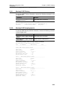
Topological Diagram
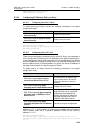
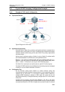
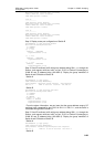
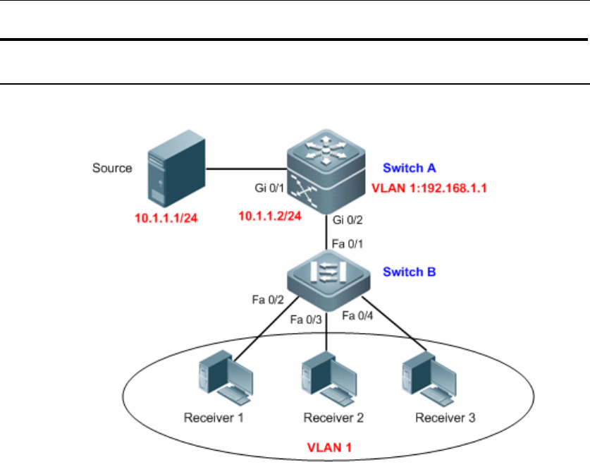
Figure4 Diagram for IVGL mode
Application Requirements
As shown above, Switch A is a multicast routing device directly connected with a
multicast source, and Switch B is a layer-2 access device connected with multiple
multicast receivers which belong to the same VLAN. The primary requirements
are shown below: :
Achieve layer-3 multicast routing on Switch A, and on Switch B, multicast traffic
won't be broadcasted on VLAN but sent to the specified receiver.
Receiver 1 can receive IP multicast traffic with group address being 224.1.1.1;
Receiver 2 can only receive IP multicast traffic with group address falling within
225.1.1.1-226.1.1.1; Receiver 3 can only join 100 IP multicast groups.
On Switch B, all access ports can quickly leave a specific IP multicast group.
On Switch B, IGMP members are prohibited from forwarding response messages
to Switch A, so as to lessen the burden of Switch A.
Configuration Tips
On the multicast routing device (Switch A), enable multicast routing and
forwarding and configure multicast routing protocol on the corresponding layer-3
interface (Gi 0/1 and VLAN 1); on the layer-2 multicast device (Switch B),
configure IGMP Snooping to operate in IVGL mode; the router port can be
generated dynamically or configured statically (configure port Fa 0/1 as the static
router port).
Configure the port directly connected with Receiver 1 (Fa 0/2) as the static
member port of corresponding group; configure IGMP Filtering on the port directly
connected with Receiver 2 (Fa 0/3); Configure the maximum number of multicast